I've been doing a lot of circuits that use logic gates recently (If you don't know about logic gates, see my last post). Today I made one which outputs "High" only if the right binary passcode is entered. It uses one four-input AND gate, formed with three ordinary AND gates, and four NOT gates, or inverters. To set a new code, I set the circuit to either use or bypass each of the inverters, which changes the passcode needed.
This passcode circuit doesn't make for a very secure system; with a four-digit binary code, there are only sixteen possible combinations. If I scaled it up, however, and added more AND gates and inverters, it would get a lot more secure, but I only have enough transistors and wires to make a four-digit passcode circuit.
There are several ways that I could have made this circuit better, if I had the resources (transistors and wires mostly). First of all, as I mentioned above, it would be much more secure if I added more digits. Eight binary digits, for example, would make 256 possible combinations, nine would make 512, and so on, which would obviously be a big improvement security wise but also very complex to build out of transistors.
Another thing I could add to improve it would be a decimal to binary encoder, which would take decimal numbers (0-9) and convert them to binary. This would mean that the passcodes could have numbers other than one and zero, which would be more like ordinary codes, but this also would take far more transistors than I own.
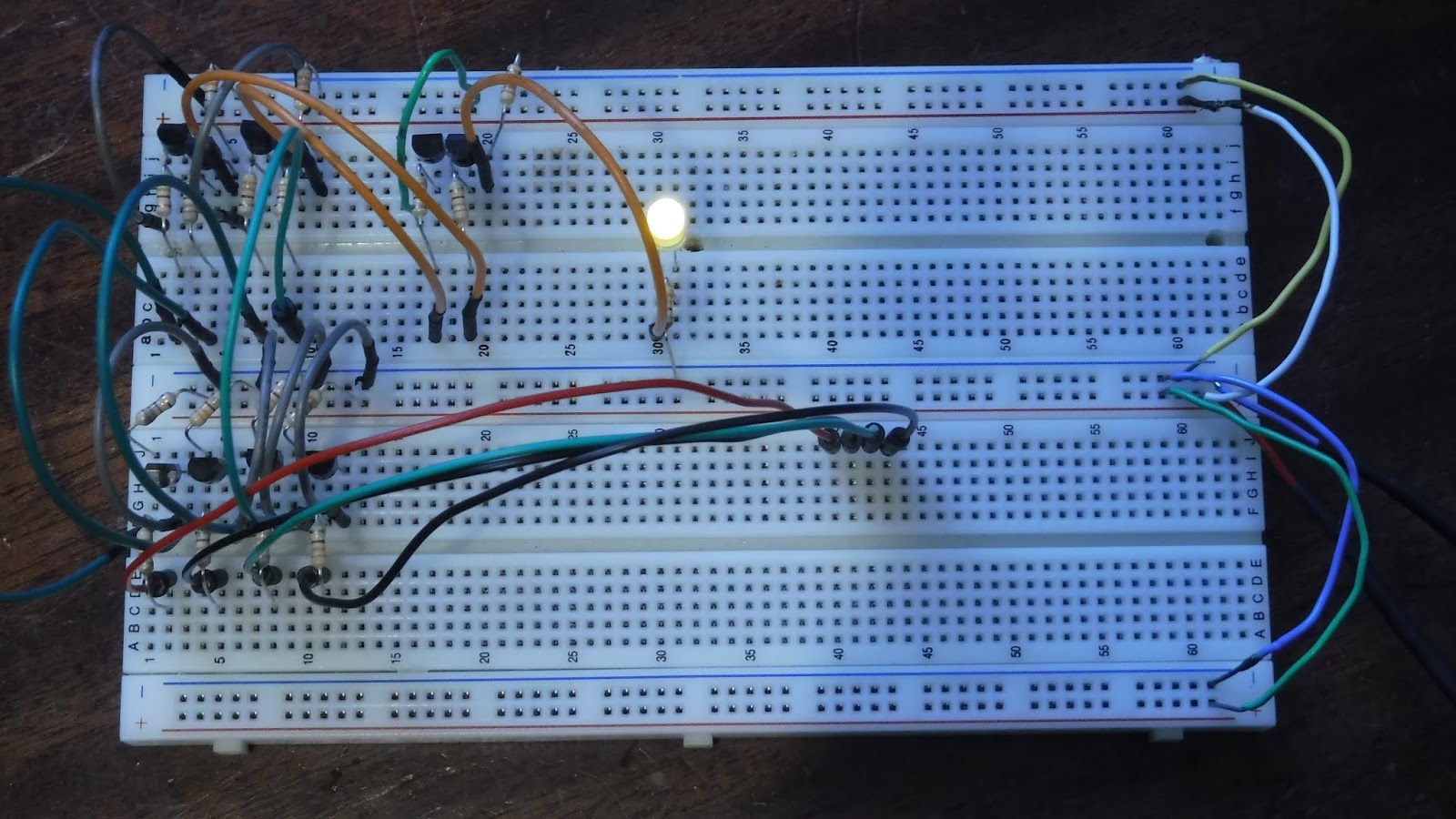
On this circuit, the input and code setting is all done without switches, simply because I don't have enough of them. To input the passcode, electrified wires are plugged into the wires leading to all the gates. If a wire is connected, it means it 1 and if there's no wire it's 0.
In this picture the code is set to 0000 (the default). No wires are plugged in, so the entered code is correct, which is why the LED is on.
In this picture the code is set to 0101, but no wires are connected, so the LED is off. At left you can see two yellow wires which are bypassing two of the inverters and making the digits 1 instead of 0.
In this picture the code is still 0101, and the correct wires are in place so the LED is on. The "code entering wires" are the yellow ones at bottom right.
The circuit, alongside a diagram showing how the gates are connected. The diagram shows switches being used to set the code, but I just connected and disconnected wires instead because I don't have any switches.
So, yesterday I made a multiplexer and today I made a flip flop (not the shoe kind). But before showing you the flip flop, here's a bit more knowledge about logic gates and digital electronics.
You might have heard that computers process information using transistors. Transistors are switches which get switched using electricity. For example, a simple use for a transistor could be to use a very small amount of electricity to switch on and off a larger amount.
You can do a lot with a single transistor, but sometimes, when you need to do something more complex (like run a computer), you will need to combine transistors into units called logic gates. logic gates are useful ways for computers to decide what to do. They have different output signals depending on the type of gate and the input signals.
There are six primary types of gates: NOT (or inverter), AND, NAND (not-and), OR, NOR (not-or), X-OR and X-NOR.
NOT gates invert the signal coming in to them, so if the input is High (electrified), than the output will be Low, and vice versa.
AND gates output Low unless both inputs are High, and OR gates output High if any or all of the inputs are High.
NAND and NOR gates stand for NOT-AND and NOT-OR respectively, and they are basically AND and OR gates with inverters attached to the outputs.
X-OR stands for exclusive-OR, which means the output is only High if one, but not both inputs are High. X-NOR gates are basically X-OR gates with an inverter attached to the output.
That might seem a little confusing to read all at once like that. Luckily, we have something called a truth table which shows what the output of the gate will be depending on the inputs. To the right are the truth tables and schematic symbols for all the gates I've mentioned, as well as a buffer, which just continues the signal from the input into the output.
These are simple gates, but more complex gates can be created with these, like three-input AND gates for example, which can created with two ordinary AND gates.
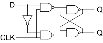
Now, about my flip-flop. A flip flop is a device made out of four NAND gates and one NOT gate (Well, mine is at least, they can be more simple or complex). A flip-flop basically is memory; it stores information and passes it on. They don't store very much information, though; one flip-flop can store one bit of information, which can either be High or Low, or, in binary, 1 or 0. To put that in perspective, modern laptops often have four gigabytes of memory. That's 32,000,000,000 bits, which really makes you appreciate what it takes to make a computer.
I set mine up with two buttons and to LEDs. One button controls the input, and one is the "clock" which advances whatever the input is into the LEDs, which light up depending on whether the input was High or Low. There is a video which might help clarify if you found that bit hard to understand.
Since it might be hard to tell what's going on in that picture, Here's a diagram which will be easier to understand, should you want to recreate this yourself: (yes, it is the same circuit, I promise)
Now, I just built this flip-flop for fun, because I just recently started having success with complicated circuits and wanted to try something interesting using gates. It's very satisfying to building something like this and have it work, but unfortunately it's usually not very practical. If you just want a flip-flop, it's much easier to use gates contained in a chip instead of making your own out of transistors, and even easier to get something like an Arduino Uno, which you can program to do whatever you want.
But that's not the point. I enjoyed myself and learned more about electronics, which is all that matters.
If you would like to learn more about logic gates, Academo's logic gate simulator is a simple simulation that allows you to create and connect logic gates and see what happens: https://academo.org/demos/logic-gate-simulator/
This circuit is called a Data Selector (or multiplexer), and it allows you to choose between two signals (or streams of data) with one input. It has three inputs; two different ones with signals, and one to choose which signal comes out the output wire.
This uses three logic gates, which are small digital circuits that perform logic operations with electric signals; for example, an AND gate's output is high (electrified) only if both inputs are high. As can be seen in the picture above, this Data Selector has two AND gates and one NOT gate, which outputs the opposite of the input signal.
My Data Selector is very small; most have many more inputs. This one probably isn't useful for anything, circuits like these are almost always parts of much more complex circuits, usually contained within chips or CPUs in electronics.
An ion thruster is a form of spacecraft propulsion that uses high voltages of electricity to accelerate gas at high velocity. Ion propulsion was used on the New Horizons spacecraft, which took the first ever close up photos of pluto. An ion thruster was chosen for New Horizons because ion propulsion is very fuel efficient. Unfortunately, it's also not very powerful, so ion propulsion is only practical in space for either very small or very long-term maneuvers.
It's turns out it's really quite easy to make an ion thruster; all I needed was a high voltage source (a neon sign transformer), a rectifier (which transforms AC electricity into DC), and a few copper pipes and nails. And the transformer and rectifier aren't even really part of the thruster; they just supply the power.
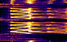
Spectrumlab is an interesting program I downloaded a while ago after seeing an interesting lecture at UBC about sound waves. So you can probably guess what it does. SpectrumLab is basically a sound visualizer, which doesn’t sound exciting, but it is, because it allows you to see sound in a completely new way. In Spectrumlab, new sounds coming in show up at the top of the screen, and their left/right positioning represents their frequency.
This image is of Spectrumlab’s output when I hummed a siren like noise, higher and lower, higher and lower. As you’ve probably noticed, the picture doesn’t just show one frequency though, so what’s up with that? As it turns out, no ordinary sound had only one frequency. Single frequency sounds can only be made electronically. The different frequencies in a sound are actually what makes sounds sound different from each other.
For example, when I hum a note and play the same one on accordion they look different in Spectrumlab.
See how the accordion note has more higher notes than my voice? That’s part of what gives accordion it’s distinct sound. Also, notice how each frequency line is actually two lines close together; that gives accordion notes a more full or “wet” feeling, and gives the sound a kind of slight vibrato because of the two frequency waves canceling each other out at regular intervals. Here’s the link to a safe download for Spectrumlab (windows only): http://www.softpedia.com/get/Multimedia/Audio/Other-AUDIO-Tools/Spectrum-Lab.shtml
Here’s some more accordion music for you to visually enjoy:
In April I was looking after a fire. We had just finished some yard work, and there were scraps to be burnt. So we made a fire, and I watched it.
Watching fires isn't very interesting. Sure, fire is cool, but after a while you're just sitting there wishing for something to do. That's what I was doing when I decided to make a knife.
Forging things isn't really very complicated, in theory. You just need to make the metal hot enough that it softens, and then smash it into shape. And then repeat, and repeat until it's the shape you want.
Now, the fire I had was big, but not very hot. Not nearly hot enough to practically forge things with. Luckily for me, fires aren't very hard to make hot. they just need air and fuel, which I had plenty of. For the air part, I connected a powerful blower to a metal ventilation tube which I aimed at the fire.
For the raw metal, I used a huge nail. I started by putting the nail in the fire and aiming the blower tube at it. It worked! The nail got red hot pretty quickly, so, I took it out of the fire with a pair of pliers to start hammering it. I did this a few times. Hammering, back in the fire, hammering, back in the fire, h- what?
Well, apparently I had left it in too long. The blade had melted away, leaving a sad jagged edge where it used to be. Let's try that again.
This time I used a bigger nail. Same process as last time, but paying more attention to how hot it's getting. And when it was the shape I wanted, I heated it up and then dipped it in water to quench it, which changes the structure of the metal to make it tougher. The forging was done! I now had a nail with a knife shape on the end. Next step: shaping.
To shape the blade, I used a Dremel (a high speed rotary tool) with a sanding bit to slowly grind away metal where I didn't want it. I also used sandpaper to properly angle the blade on the cutting side, and start to sharpen it. finally, I used a cutting bit to cut the 'handle' to the right length.
Shaping the knife
To finish the handle, I thought string would work well, so I tried winding it up with some ordinary white string. It looked great! I took the string off and did it again, this time gluing it on as I wound. It might seem like this wouldn't make a very strong handle, but in reality it works very well, as well as looking and feeling very nice. It's wound so evenly you can hardly tell it's string!
The last step was sharpening. I had thought it was sharp enough before, but I changed my mind. I decided I needed a sharper angle on the blade, so I took out a grinding wheel and ground! When I was done that it still wasn't sharp enough, so I used a couple sharpening stones. Then, finally, I was satisfied.
I've had and been making this robot since around October, and now I've finally decided it's complete!
Here's the story of it's creation.
I used to take apart Roombas. You know, the robotic vacume that cleans your floor automatically? Right. I took them apart. Three of them, which I found at my local recycling depot. I would start by pulling out the bits that are meant to be unattached; the dust tray and the sweeper and the other thing. I'm not sure what to call it, it's kind of a rubber carpet whacker connected to the sweeper, probably makes it vacume better or something.
Anyway, I would start by taking all those things out, and then I would unscrew and rip the top off to expose the insides of the vacume. There's a lot inside a Roomba. Lots of sensors, switches and wires, which are nice, but the parts I liked the most were the two wheel units.
Each one is a motor connected to a big, knobbly wheel, all well behaved and self contained in a plastic case, with two wires sticking to control the motor, and four others connected to a rotation sensor. And I had six of them! As soon as I saw them all together it was obvious I would have to make a robot.
This was the first stage of robot construction: Hot glue and popsicle sticks.
Quickly after deciding to build a robot, and after a few false starts (you can see the remains of one in the background), I put that together. I decided to go simple: skid steering (like an excavator), and four wheels. Although conventional steering might have been more efficient, it was out of the question; Much to complicated, and likely to break (well, more like doomed to break. It's my robot, after all). And yes, six wheels would have been cooler, but it would also mean the robot would have to be longer, which would mean the skid steering would be even less efficient, to the point of not working at all.
After building that, I wasn't really sure what to do next. I have an Arduino, which is basically a tiny computer that you can control electronics with. I knew I wanted to use it as the brain of my robot, but I didn't know how. I couldn't connect the motors directly to the Arduino- it doesn't put out nearly enough power, and the motors create spikes in the electricity that could damage my Arduino. So, I did some research.
According to what I found on the internet, in order to control my robot I needed something called an H-bridge. An H-bridge is kind of like a complex electric switch. Two of it's wires are connected to a motor, two to a power supply, and another two are connected to whatever you controlling the motor with (in my case, my Arduino). Putting power through one of the controller wires makes the H-bridge power the motor in either one direction or another. That seemed straightforward enough, so I went to an electronics store to buy a couple.
I came back from the electronics store not with H-bridges, but with an Osep Motor Shield, which is basically a bunch of H-bridges incorporated onto a circuit board which plugs into the top of an Arduino. "Even better!" I thought. Now I just needed to figure out how it worked. That was harder then I thought it would be.
The Osep motor shield
I looked online, but there was literally nothing that explained how to use it. But eventually I figured it out. I thought. It turned out I needed to program it with some commands for a different motor controller. Great! So I tried writing code to make the robot go, but it didn't work. Then I copied someone else's. It's still didn't work. Then I switched a couple of wires around. Guess what... they had been backwards. It ran fine! I strapped it to my robot, and it ran beautifully.
I made this diagram after figuring out how everything works.
All it could do was repeat a series of movements that I programmed it to do, but that was OK with me. Now I just had to figure out how to power it.
I had previously been using a variable voltage power supply to power it, but that power supply plugs into the wall and I wanted my robot to be free. I tried some small hobby batteries I have, but they weren't strong enough and I had no way to charge them. And ordinary consumer batteries were out of the question. Not only would they run out of power fast, they would be way to expensive.
I put the problem aside for a while and made the body of the robot bigger. More room for a battery, if I ever found one. And then I remembered something. The three Roombas I took apart had batteries! And they were the perfect size, too. I just needed a way to charge them. Luckily, I have an Irobot (the company that makes Roombas) power supply. I could charge the battery with that. I just needed to find out how. Usually the power supply would charge the battery while it was still in the vacume, so I couldn't just plug it in. But I watched a couple of videos about it, and decided to try wiring the battery directly to the charger. It was a bit scary, but it worked! the battery charged. My robot was free!
The Roomba wheels
A Backyard Adventure!
I wasn't sure what to do next. There were several options. I could make it into a true robot by giving it sensors and programing it to use them, which would mean it could theoretically drive around by itself, or I could have made it remote control, so that I could drive it around places without pre-programming all it's movements.
What I really need is a use for it. And I don't have one yet.
So I decided to let it wait, and be finished for now.
I will find something for it to do eventually, but for now you can enjoy this montage of it's adventures outside! Music: Hans Hylkema, Backyard Adventure