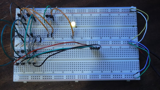
This passcode circuit doesn't make for a very secure system; with a four-digit binary code, there are only sixteen possible combinations. If I scaled it up, however, and added more AND gates and inverters, it would get a lot more secure, but I only have enough transistors and wires to make a four-digit passcode circuit.
There are several ways that I could have made this circuit better, if I had the resources (transistors and wires mostly). First of all, as I mentioned above, it would be much more secure if I added more digits. Eight binary digits, for example, would make 256 possible combinations, nine would make 512, and so on, which would obviously be a big improvement security wise but also very complex to build out of transistors.
Another thing I could add to improve it would be a decimal to binary encoder, which would take decimal numbers (0-9) and convert them to binary. This would mean that the passcodes could have numbers other than one and zero, which would be more like ordinary codes, but this also would take far more transistors than I own.
On this circuit, the input and code setting is all done without switches, simply because I don't have enough of them. To input the passcode, electrified wires are plugged into the wires leading to all the gates. If a wire is connected, it means it 1 and if there's no wire it's 0.
 |
| In this picture the code is set to 0000 (the default). No wires are plugged in, so the entered code is correct, which is why the LED is on. |
 |
| In this picture the code is still 0101, and the correct wires are in place so the LED is on. The "code entering wires" are the yellow ones at bottom right. |


No comments:
Post a Comment