Pages

Sunday, February 3, 2019

Simple Passcode Circuit

I've been doing a lot of circuits that use logic gates recently (If you don't know about logic gates, see my last post). Today I made one which outputs "High" only if the right binary passcode is entered. It uses one four-input AND gate, formed with three ordinary AND gates, and four NOT gates, or inverters. To set a new code, I set the circuit to either use or bypass each of the inverters, which changes the passcode needed.

This passcode circuit doesn't make for a very secure system; with a four-digit binary code, there are only sixteen possible combinations. If I scaled it up, however, and added more AND gates and inverters, it would get a lot more secure, but I only have enough transistors and wires to make a four-digit passcode circuit.

There are several ways that I could have made this circuit better, if I had the resources (transistors and wires mostly). First of all, as I mentioned above, it would be much more secure if I added more digits. Eight binary digits, for example, would make 256 possible combinations, nine would make 512, and so on, which would obviously be a big improvement security wise but also very complex to build out of transistors. 
Another thing I could add to improve it would be a decimal to binary encoder, which would take decimal numbers (0-9) and convert them to binary. This would mean that the passcodes could have numbers other than one and zero, which would be more like ordinary codes, but this also would take far more transistors than I own.

On this circuit, the input and code setting is all done without switches, simply because I don't have enough of them. To input the passcode, electrified wires are plugged into the wires leading to all the gates. If a wire is connected, it means it 1 and if there's no wire it's 0.

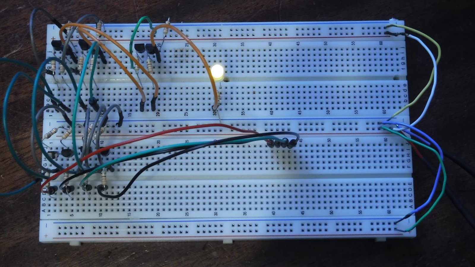
In this picture the code is set to 0000 (the default). No wires are plugged in, so the entered code is correct, which is why the LED is on.

In this picture the code is set to 0101, but no wires are connected, so the LED is off. At left you can see two yellow wires which are bypassing two of the inverters and making the digits 1 instead of 0.

In this picture the code is still 0101, and the correct wires are in place so the LED is on. The "code entering wires" are the yellow ones at bottom right.

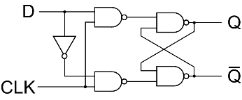
The circuit, alongside a diagram showing how the gates are connected. The diagram shows switches being used to set the code, but I just connected and disconnected wires instead because I don't have any switches.

Saturday, February 2, 2019

I Also Made a Flip Flop

So, yesterday I made a multiplexer and today I made a flip flop (not the shoe kind). But before showing you the flip flop, here's a bit more knowledge about logic gates and digital electronics.

You might have heard that computers process information using transistors. Transistors are switches which get switched using electricity. For example, a simple use for a transistor could be to use a very small amount of electricity to switch on and off a larger amount.
You can do a lot with a single transistor, but sometimes, when you need to do something more complex (like run a computer), you will need to combine transistors into units called logic gates. logic gates are useful ways for computers to decide what to do. They have different output signals depending on the type of gate and the input signals.

There are six primary types of gates: NOT (or inverter), AND, NAND (not-and), OR, NOR (not-or), X-OR and X-NOR.

  • NOT gates invert the signal coming in to them, so if the input is High (electrified), than the output will be Low, and vice versa. 
  • AND gates output Low unless both inputs are High, and OR gates output High if any or all of the inputs are High. 
  • NAND and NOR gates stand for NOT-AND and NOT-OR respectively, and they are basically AND and OR gates with inverters attached to the outputs.
  • X-OR stands for exclusive-OR, which means the output is only High if one, but not both inputs are High. X-NOR gates are basically X-OR gates with an inverter attached to the output.


That might seem a little confusing to read all at once like that. Luckily, we have something called a truth table which shows what the output of the gate will be depending on the inputs. To the right are the truth tables and schematic symbols for all the gates I've mentioned, as well as a buffer, which just continues the signal from the input into the output.

These are simple gates, but more complex gates can be created with these, like three-input AND gates for example, which can created with two ordinary AND gates.

Picture from http://www.nutsvolts.com/magazine/article/understanding_digital_buffer_gate_and_ic_circuits_part_1


Now, about my flip-flop. A flip flop is a device made out of four NAND gates and one NOT gate (Well, mine is at least, they can be more simple or complex). A flip-flop basically is memory; it stores information and passes it on. They don't store very much information, though; one flip-flop can store one bit of information, which can either be High or Low, or, in binary, 1 or 0. To put that in perspective, modern laptops often have four gigabytes of memory. That's 32,000,000,000 bits, which really makes you appreciate what it takes to make a computer.

I set mine up with two buttons and to LEDs. One button controls the input, and one is the "clock" which advances whatever the input is into the LEDs, which light up depending on whether the input was High or Low. There is a video which might help clarify if you found that bit hard to understand.

Since it might be hard to tell what's going on in that picture, Here's a diagram which will be easier to understand, should you want to recreate this yourself: (yes, it is the same circuit, I promise)
From https://electronicsforu.com/resources/learn-electronics/flip-flop-rs-jk-t-d

Now, I just built this flip-flop for fun, because I just recently started having success with complicated circuits and wanted to try something interesting using gates. It's very satisfying to building something like this and have it work, but unfortunately it's usually not very practical. If you just want a flip-flop, it's much easier to use gates contained in a chip instead of making your own out of transistors, and even easier to get something like an Arduino Uno, which you can program to do whatever you want.

But that's not the point. I enjoyed myself and learned more about electronics, which is all that matters.


If you would like to learn more about logic gates, Academo's logic gate simulator is a simple simulation that allows you to create and connect logic gates and see what happens: https://academo.org/demos/logic-gate-simulator/

I Made a Data Selector


This circuit is called a Data Selector (or multiplexer), and it allows you to choose between two signals (or streams of data) with one input. It has three inputs; two different ones with signals, and one to choose which signal comes out the output wire.

This uses three logic gates, which are small digital circuits that perform logic operations with electric signals; for example, an AND gate's output is high (electrified) only if both inputs are high. As can be seen in the picture above, this Data Selector has two AND gates and one NOT gate, which outputs the opposite of the input signal.

My Data Selector is very small; most have many more inputs. This one probably isn't useful for anything, circuits like these are almost always parts of much more complex circuits, usually contained within chips or CPUs in electronics.

Tuesday, January 8, 2019

I finally built my ion thruster

An ion thruster is a form of spacecraft propulsion that uses high voltages of electricity to accelerate gas at high velocity. Ion propulsion was used on the New Horizons spacecraft, which took the first ever close up photos of pluto. An ion thruster was chosen for New Horizons because ion propulsion is very fuel efficient. Unfortunately, it's also not very powerful, so ion propulsion is only practical in space for either very small or very long-term maneuvers.

It's turns out it's really quite easy to make an ion thruster; all I needed was a high voltage source (a neon sign transformer), a rectifier (which transforms AC electricity into DC), and a few copper pipes and nails. And the transformer and rectifier aren't even really part of the thruster; they just supply the power.